How many Touch-Tone digits does your landline have? 12 ? …That’s so pedestrian.
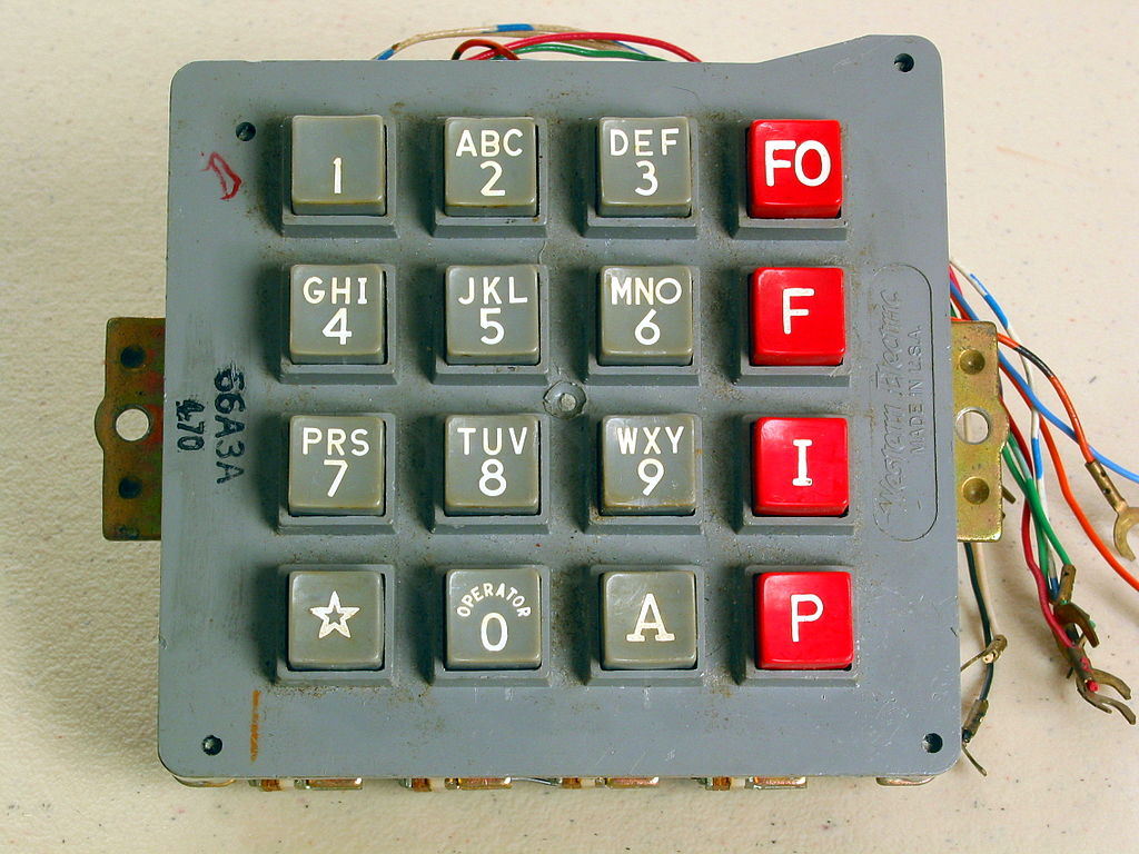
If you’re a phone geek you might know about the old military AUTOVON phone system.
These phones added 4 additional digits, that could be used to indicate the urgency of the call.
P for priority, I for immediate, and F for flash
If all the lines were tied up, and you were an important enough person with an important enough call, there was also FO, Flash Override. Ooh, that sounds cool, other calls be damned, we need to tell SAC to recall those bombers STAT!
Each button on a Touch-Tone dial produces a different tone. Technically each button produces not one, but two different tones
Touch-Tone dialing is part of something we call DTMF, dual tone multi-frequency signaling
This makes it easier for equipment to detect key presses. Background noise, or even the sound of someone’s voice might trick a tone detector into thinking it has one of the tones, but it’s far less common to falsely detect the presence of both tones at the same time.
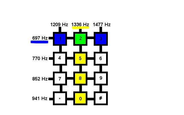
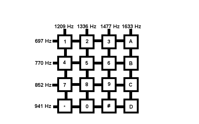
The dual tones of DTMF come from the combination of a row tone and a column tone. Each column produced one of the two tones, and each row produced the other
For example, the numbers 1, 2, and 3 all share the frequency 697 Hz in common and the numbers 2, 5, 8, 0 all share 1,336 Hz in common but only the number 2 is made up of both 697 Hz and 1,336 Hz
AUTOVON used an extra column of 1,633 Hz to add the additional four buttons.
This 4th column isn’t exclusive to AUTOVON. It may not be common, but it can be found in use in various telecommunications applications. For instance AMIS, the Audio Messaging Interchange Specification (which is used to transmit voicemail messages between different systems) uses these additional 4th column tones.
When these fourth column buttons are used outside of AUTVON we usually refer to them as, A, B, C, and D (rather than FO, F, I, and P respectively)
Imagine what you could do with an extra set of digits. Maybe add an extra layer of obscurity to your voicemail password, no more 1234 for me, but maybe 123ABC ? Add secret debug menus to your interactive voice response menus and Asterisk Gateway Interface scripts. Unlock an extra octave in your DTMF song performances. Exciting stuff.. surely.
You can sometimes find old AUTOVON phones on eBay, but they generally go for more money than I’d consider spending.
Are you sensing a project? You’re right!
Phone phreaks have used various gizmos over the years to produce tones and explore or just rip-off phone networks.
Possibly in tribute to Steve Wozniak‘s little blue box that allowed him to explore the in-band signalling of the long distance trunk lines of yesteryear, these devices were commonly called boxes, and the purpose of the device was identified by a color.
There’s a whole rainbow of colored boxes out there, for example If you were tricking a payphone into thinking you just deposited a quarter you were red boxing.
One of these so-called boxes was the Silver Box, a device to generate these 4th column tones.
One of the simplest versions of the silver box involved modifying an existing phone by adding a toggle switch to switch the last column 3, 6, 9, # from 1,477 Hz to 1,633 Hz. If you were lucky enough your phone might even have a local oscillator generating the 1,633 Hz tone (if not, you’d need to create a circuit to generate it).
To make my silver box I’m going to combine the best parts of to two different phones
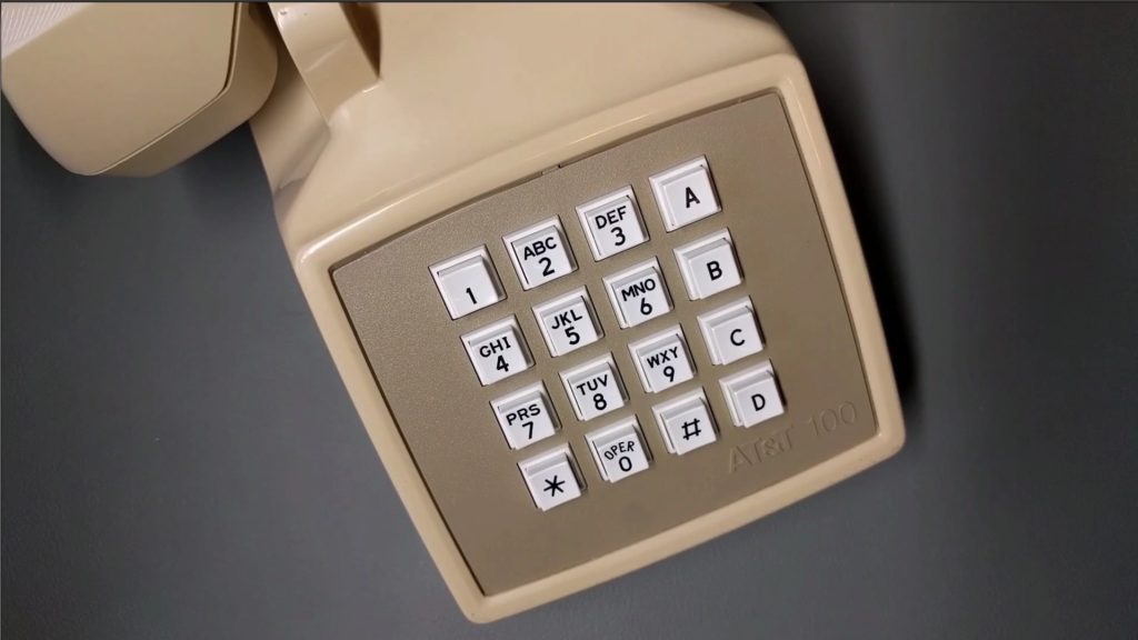
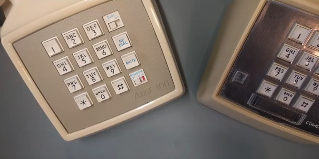
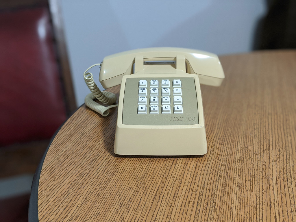
On the left is an AT&T Traditional 100, it’s going to be the body of my phone, and I’ll be using most of its original electronics. The idea for this project came while I was looking at a picture of this phone. I thought, “huh, this extra column of buttons and switches over on the right looks evenly spaced and sized with the other buttons. I wonder if I could replace the keypad without having to modify the the phone.”
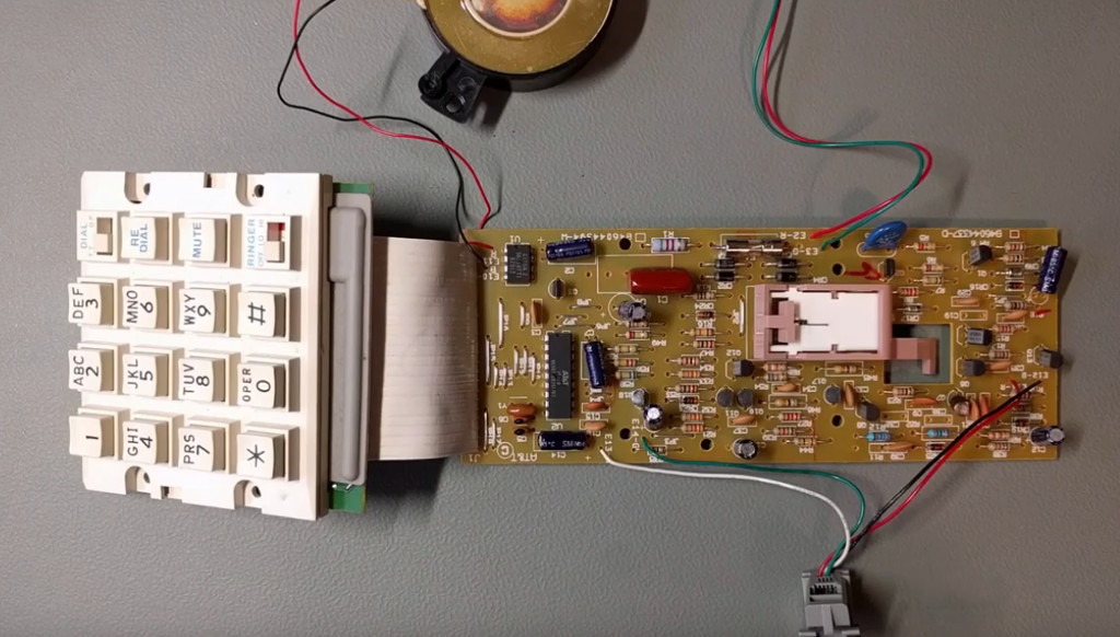
On the right, is a COMDIAL 2579 (or at least I think that’s the model number). I’m going to be using some of its dialing guts for the project, to see why, lets take a closer look.
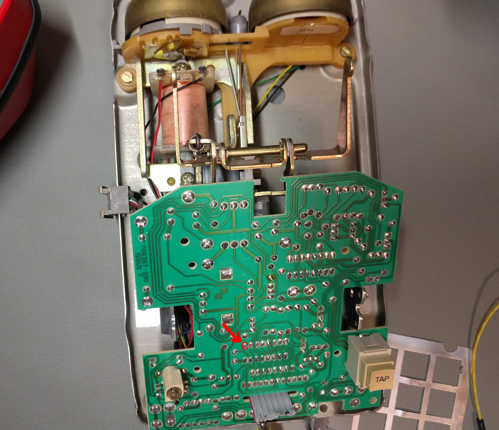
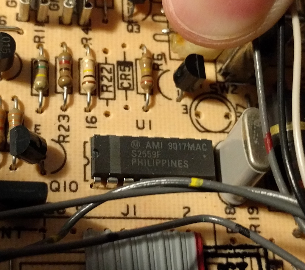
Popping the top off the phone we can see a 16-pin DIP IC soldered to the PCB. One of the pins doesn’t appear to have any traces drawn to it.
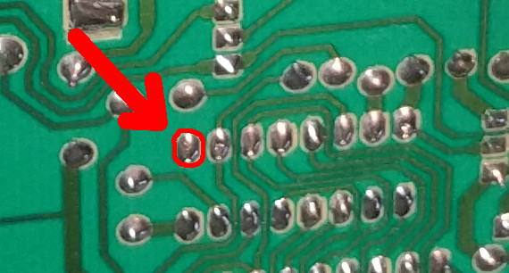
Here is a closer look at that DIP layout
Removing the PCB and flipping it over we can get a closer look at that IC.
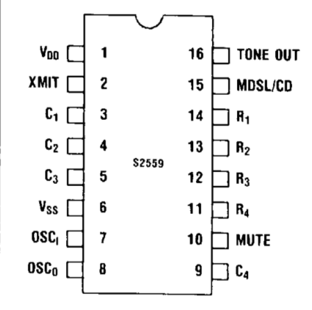
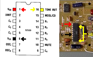
It’s labeled AMI S2559F (American Microsystems Incorporated). Searching for the product datasheet online gives us the pin-out. We can see that pin 9 that wasn’t connected to any traces on the PCB corresponds to C4 (column 4).
I removed this chip and the required (common 3.58 MHz TV crystal) oscillator (connected to pins 7 & 8) from the COMDIAL PCB and transplanted them onto a piece of perfboard.
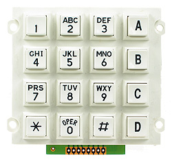
There are a lot of 4×4 keypads out there, but the one I bought came from Futurlec. I like this one because it looks like it belongs on a phone (it has the traditional letters above the numbers, and OPER above the 0 key). I wired it up to the pins of the S2559F using AMI’s datasheet.
I used a multimeter set in continuity testing mode to identify how to wire up my keypad.
Pin 1 of the keypad corresponded to the 2nd row (4, 5, 6, B). Pin 2 to row 3 (7, 8, 9, C), Pin 3 to column 1 (1, 4, 7, *), Pin 4 to row 4 (*, 0, #, D). Pin 5 to column 2 (2, 5, 7, 9, 0). Pin 6 to column 3 (3, 6, 9, #). Pin 7 to column 4 (A, B, C, D). Pin 8 to row 1 (1, 2, 3, A).
_______
1|2|3|A| Pin 8
4|5|6|B| Pin 1
7|8|9|C| Pin 2
*|0|#|D| Pin 4
-------
3 5 6 7 <-Pins
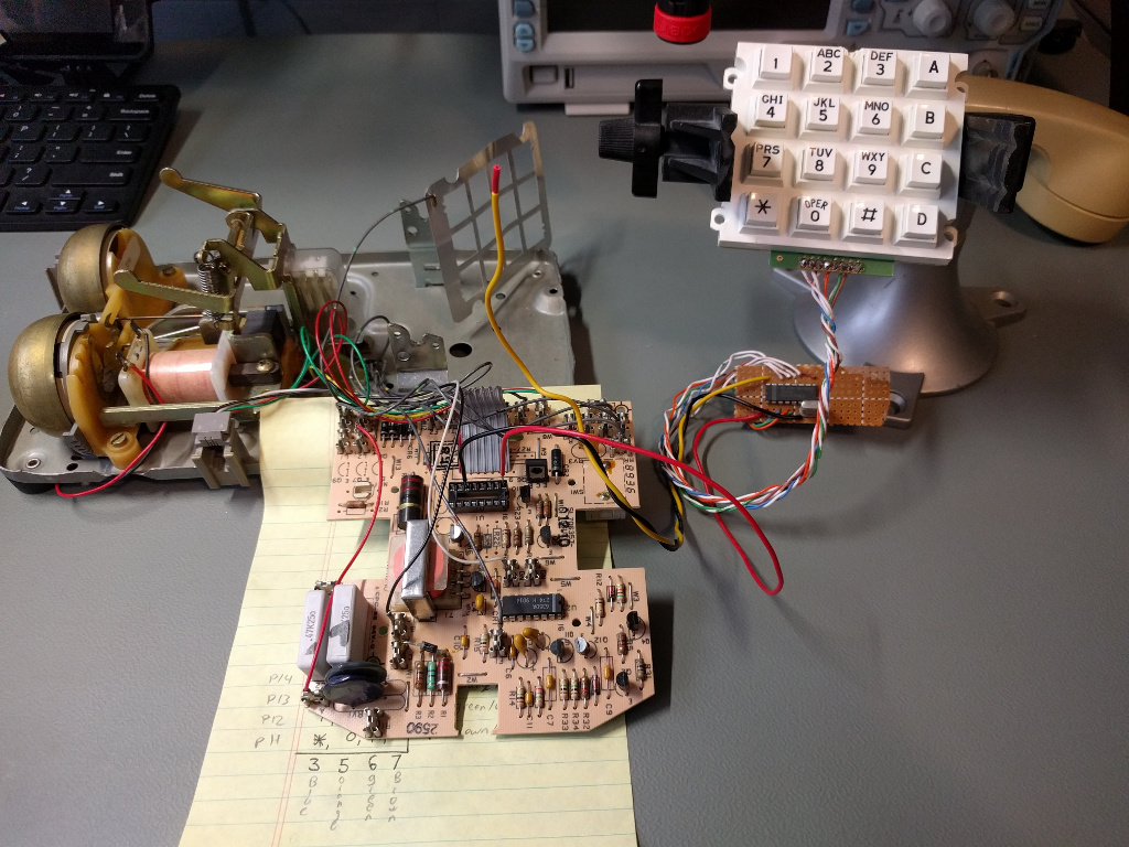
After successfully testing the circuit connected to the COMDIAL PCB I began working on integrating the perfboard and keypad into the body of AT&T Traditional 100.
I removed the AT&T Traditional 100 PCB from its housing and removed the 18-pin IC to begin work on guessing the pin-outs. Unfortunately this IC is pretty uncommon, and I wasn’t able to find a datasheet to help me along.
On pin 1 (VDD) of the AT&T 18 pin IC I found sufficient voltage for the S2559F. According to the datasheet, to operate (generate a tone) the S2559F needs around 2.5 VDC, but can work with as much as 10 VDC. Pin 6 (VSS) seemed to be a good ground. To get a tone to play I needed to bridge pins 10 & 17 (TONE OUT) and inject the tone-out pin of the S2559F to that connection.
Here is an illustration of how I hooked it up
This all seemed to work pretty well, and I’m happy with the results even if I don’t really have that much use for the phone itself. I suppose if you are going to keep a landline around the house, might as well keep an interesting one.
I suppose it might not be totally correct to call this a landline. I have it connected to an analog telephone adapter for VoIP (that I own). You probably don’t want to go about connecting hacked up telephony equipment to lines that aren’t your own. In some jurisdictions this might even be illegal (oh, that sounds like a disclaimer! old school. Nice).
Have Phun!
