Project Introduction
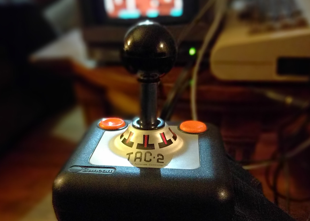
I made an adapter to take classic video game controllers for Sega, Atari (2600, 7800) and Commodore (VIC20, C64, C128) and adapt them to work as a 5 button USB keyboard (4 directions and a fire/trigger key).
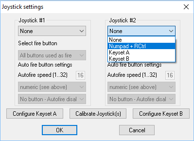
The joystick now works like an external numeric keypad. Pressing the fire/trigger button will act like pressing the right-hand Control/Ctrl key. This was all written in the Arduino IDE, and can be easily changed (if for example you prefer using W,A,S,D for direction and space bar to fire, or the arrow keys for movement, it’s a quick change to make.
I picked this configuration mostly because the C64 emulator VICE has it as an option.
Hardware
For the brains I used a board with an Atmel ATMega32U4, similar to the Arduino Pro Micro (see parts list below).
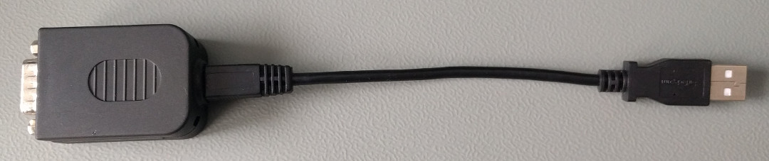
As an enclosure I used a DE-9 adapter housing. This one had terminal blocks for quickly throwing cables together, which I removed to make room.
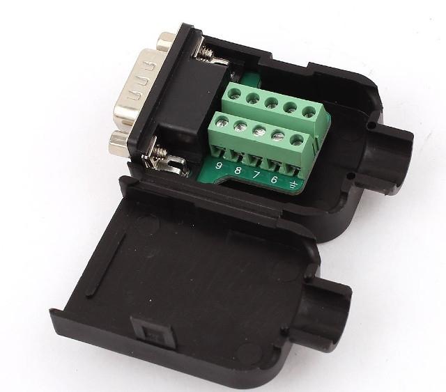
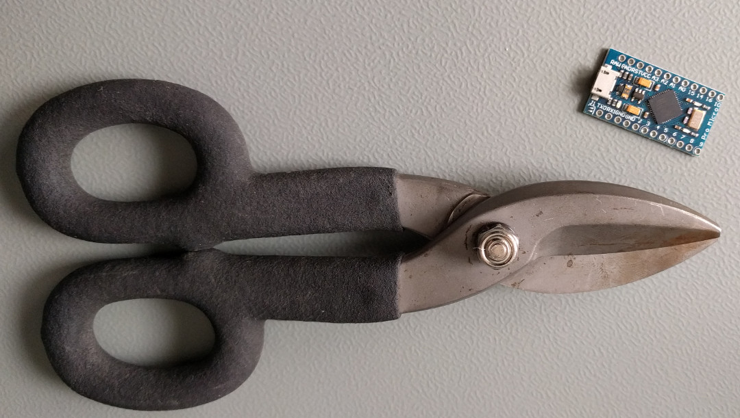
I chose this particular DE-9 adapter because it looked like it might be roomy enough to put the microcontroller into, however it wasn’t quite long enough. So, with some heavy duty cutters I use for chomping up bits of PCB I cut the last two pin holes off the microcontroller board.
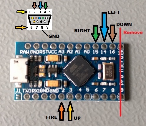
After cutting I sanded the edge and visually inspected to try to make sure no obvious unexpected connections between layers were being made. Cutting this down gave me enough room to fit it into the enclosure. I’ve shown this modification in the microcontroller PCB image below as a red line through the PCB.
I soldered up some wires between the DE-9 PCB and the microcontroller PCB. The silk screen of the DE-9 PCB made it easy to quickly identify which pins were which. The I/O pins I chose on the microcontroller were really just a matter of convenience to get the cables to cooperate nicely with the DE-9 PCB and leave enough room to close the adapter enclosure. I didn’t annotate it very well in the image below, but the DE-9 ground (GND) pin should be wired to any one of the available microcontroller GND pins.
To prevent accidental electrical connections between microcontroller PCB and the DE-9 PCB I wrapped the microcontroller in some Kapton tape, but hot glue or something would probably work fine. The end result looks like a big mess, thankfully I don’t have to look at it with the enclosure closed.
I ended up needing to use a hobby knife to carve out a little of the cable opening of the DE-9 enclosure to widen it for the USB micro connector end.

Software
To find the numeric keypad directional key values I referenced the USB HID Usage Tables found here:
http://www.usb.org/developers/hidpage/Hut1_12v2.pdf
A quirk of the Arduino USB keyboard report handling requires you to add 136 (decimal) to the value you find in the usage table. This value is later removed by other code in the USB library, but helps the source make some kind of determination on how to handle the key event (it seems pretty crazy to me too, but whatever, it works).
Because the board I’m using has an ATmega32U4 with an Arduino bootloader it shares enough in common with the Arduino Leonardo that “Arduino Leonardo” should be selected as the target board in the Arduino IDE to properly compile and flash the software.
// Some more meaningful names for referencing applicable I/O pins
#define FIRE_PIN  2
#define UP_PIN  3
#define DOWN_PIN  16
#define RIGHT_PIN  15
#define LEFT_PIN  14

// Arduino-friendly (value+136) keyboard values of direction keys of numeric keypad
#define KEY_PAD_UP 232
#define KEY_PAD_DOWN 226
#define KEY_PAD_RIGHT 230
#define KEY_PAD_LEFT 228

// Map a keyboard value to the input pin. First Pins[] value is first Keys[] value, etc
byte Pins[] = {FIRE_PIN,        UP_PIN,     DOWN_PIN,     RIGHT_PIN,     LEFT_PIN    };
byte Keys[] = {KEY_RIGHT_CTRL,  KEY_PAD_UP, KEY_PAD_DOWN, KEY_PAD_RIGHT, KEY_PAD_LEFT};

void setup() {
  // pullup all button input pins to high
  for (int i = 0; i <= sizeof(Pins); i++) {
    pinMode(Pins[i], INPUT_PULLUP);
  }

  Keyboard.begin();
}

void loop() {

  {
    int keyStates = 0;
    for (int i = 0; i <= sizeof(Pins); i++) {
      if (digitalRead(Pins[i]) == LOW) {
        Keyboard.press(Keys[i]);
        keyStates = 1;
      }
    }
    if (keyStates == 1) {
      // pause a moment to give any pressed keys a chance to report,
      // and possibly ignore some joystick bounce as well
      delay(10);
    }
  }

  // Release any keys that need to be released
  for (int i = 0; i <= sizeof(Pins); i++) {
    if (digitalRead(Pins[i]) == HIGH) {
      Keyboard.release(Keys[i]);
    }
  }

  // If no buttons are being pressed, releaseAll() to ensure no keys are stuck down
  {
    int pinStates = 1;
    for (int i = 0; i <= sizeof(Pins); i++) {
      pinStates = pinStates & digitalRead(Pins[i]);
    }
      if (pinStates == HIGH) {
        Keyboard.releaseAll();
      }
  }

}
Here is a description of what the code is doing.
#defines
The source defines some names for the pins that connect to the corresponding DE-9 pins (see the “Hardware” notes above for clarification) and some names for the keypad values. The right-hand Ctrl key value(KEY_RIGHT_CTRL) is already defined in the Arduino USB library.
setup()
The connected pins are internally pulled high, and are considered activated when connected to ground through the normal use of the joystick. The pins to be monitored for these state changes are put into the Pins[] array and the corresponding key values to send in the USB report are put in the Keys[] array at the respective array index position.
The function setup() gets ran at device power-up and loops through all the pins listed in Pins[] to configure the internal pullup to high state. Keyboard.begin() prepares the Arduino keyboard library.
loop()
The main loop() iterates through each pin in Pins[] looking for a low state and applicably sets the corresponding key. If any keys are found to be pressed a ~10ms pause occurs to allow the operating system ample time to see the USB report, but not offer too much delay as to cause the joystick to feel unresponsive to rapid changes. This delay also helps remove sporadic changes in pin state due to imperfect contact between the joystick internal connection plates. Another iteration through the Pins[] array occurs to remove the appropriate data from the USB report for any keys no longer being held down. A final (possibly unnecessary) check occurs which calls Keyboard.releaseAll() when no positions of the joystick are active (low). I had some issues during initial develop with keys getting stuck “down” and found it very irritating to have to physically unplug the adapter in order to resolve the problem. This check was added to make life a little easier, but may no longer be required. Keyboard.releaseAll() only removes reports from memory on the microcontroller and won’t cause the USB host to ignore held keys on other connected keyboards, so it seems harmless enough to leave in place.
Bill of Materials
Arduino Pro Micro-like board
https://www.amazon.com/gp/product/B012FOV17O
“DB9” / DE-9 9 pin adapter module (terminal blocks will need to be removed)
https://www.amazon.com/gp/product/B00YM3W7OI
Micro USB cable
https://www.amazon.com/gp/product/B003YKX6WM
Resources
USB HID Usage Tables
http://www.usb.org/developers/hidpage/Hut1_12v2.pdf
-Have fun!