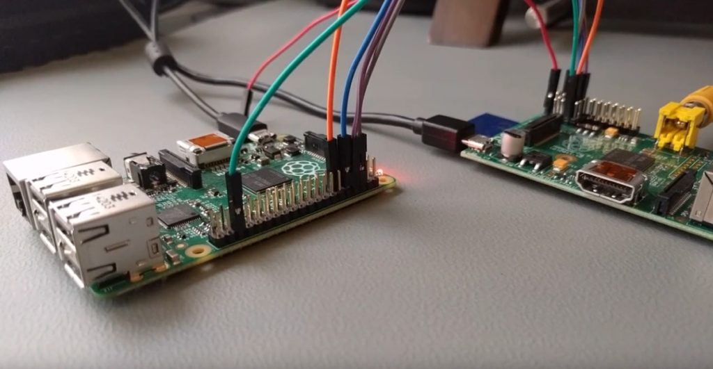
I had need of a 3.3v TTL serial interface to reprogram a device I was working on. Looking around I realized I had mostly 5v logic USB to serial adapters. I figured the Raspberry Pi would work well enough, but I also needed hardware flow control. As it turned out the Pi can do RTS / CTS flow control, so I documented my notes on the subject here in case I or someone else might find them useful in the future.
What is flow control
In serial communications occasionally we need a way to tell the device or computer on the far-end of our serial connection that we need it to shut up for a bit while we collect our thoughts. Flow control exists for this purpose, although it is not a requirement of serial communication. Modern devices are fast, with large buffers for collecting incoming data, and often times flow control is omitted, particularly if data loss isn’t critical.
Flow control can be done in software (Xon/Xoff) by sending special control characters to say stop or start the data flow. This creates some hassle since, particularly in the transmission of binary data, those control characters might come up naturally without the intent to change the flow of data. If you’ve ever accidentally frozen your Linux terminal (^s / ^q) you know what I’m talking about.
Flow control can also be done out of band of the data transmission using dedicated signal pins/wires, we call this hardware flow control. Serial communications are old, there are a lot of variations so it probably isn’t much of a surprise to learn that there are multiple ways of doing hardware flow control. The most common are RTS / CTS and DTR / DSR. We are focusing on RTS / CTS, although DTR is still useful to know about (it gets used for example in programming the Arduino, to trigger a reset of the Arduino before programming). Because we can arbitrarily set the state of RTS and DTR via software we can abuse them to signal all sorts of stuff to connected hardware beyond just flow control.
RTS stands for “Request to Send”, and in the current common use it is a terrible name for what it actually does. The name implies that it signals a request to send data to the equipment on the other side of the serial connection. CTS stands for “Clear to Send”, and as we might (correctly) assume it is a signal being sent to us from the far-end that indicates we are cleared to send our data. The problem with this is that it is only half-duplex (it goes just one way). How could we tell the far-end that we aren’t ready to receive data? Originally this was actually how it worked, it was intentionally half-duplex and it was designed with some rather old modem technology in mind.
RTR or “Request to Receive” is probably a better name for RTS as it is used today, and some people prefer to use this term instead. We, or rather the UART controlling our communication doesn’t actually change the state of RTS when it wants to transmit data. RTS/RTR gets changed when the UART is unable to receive any more data from the far-end. This probably indicates that our hardware receive buffer is full and hasn’t been read and emptied out by software on our system yet.
On the Raspberry Pi RTS is set low (0v) as long as the Pi’s UART is ready to receive data. If it can’t handle more incoming data it sets RTS high (3.3v). Our Pi should only send data to the far-end when the state of our CTS pin reads low and we should stop sending data if our CTS pin is high. So now we’ve got a working plan for bi-directional flow control. Our RTS goes to the CTS of the far-end and the far-end RTS goes to our CTS (and hopefully we both agree on the logic levels).
In our serial connection RTS and TX are our outputs, and CTS and RX are our inputs.
Where are the RTS / CTS pins?
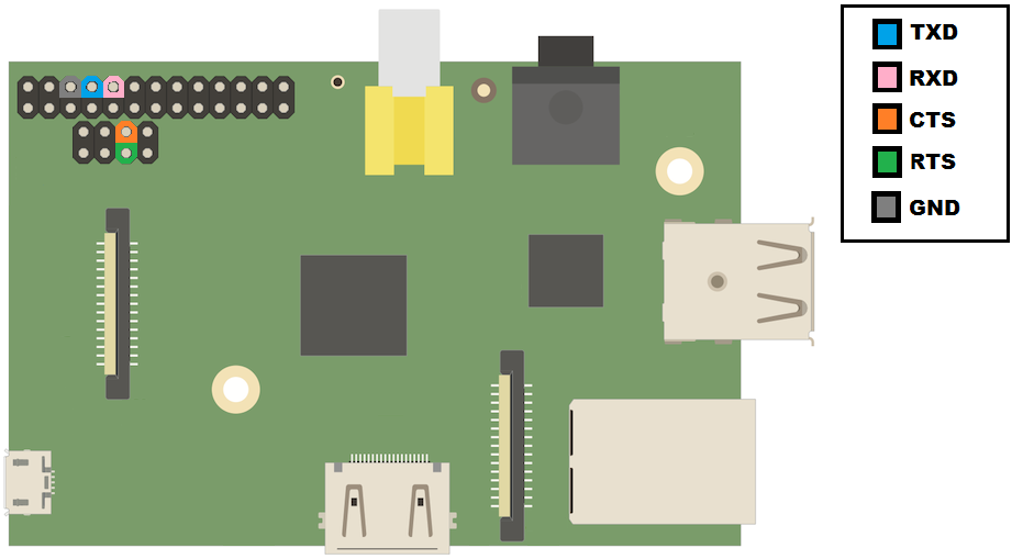
On older versions of the Raspberry Pi with 26-pin GPIO header, you need to solder on an additional 2×4 section of dual row male 0.1″ (2.54mm) header pins on the unpopulated “P5” header.
On early Pi’s like the original version B, this header isn’t there, and so if you are still using one of those devices you’ll probably need to work something else out.
The P5 header is actually intended to be mounted on the bottom of the Pi board (opposite to the 26 pin GPIO). That seemed pretty crazy to me, because the thing would obviously never lay flat or fit in standard cases that way. I think the intent is to avoid interfering with Raspberry Pi hats that sit on top of the 26-pin header, but even with P5 populated on the reverse side of the board (same side as the 26-pin headers) I was able to put the one hat I have on my Pi. Your miles may vary of course. If you do put the P5 header on the same/sane side of the board as the 26 pin header keep in mind that many of the pin-outs you run into online might be mirrored.
To remove ambiguity I’ve just colored the correct pins below rather than giving pin or GPIO numbers:
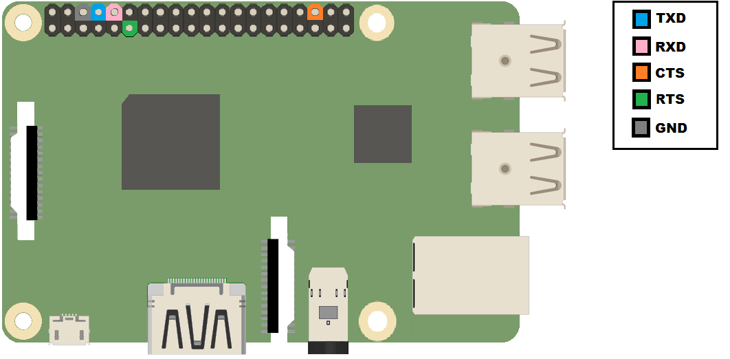
On newer Raspberry Pis with the 40-pin header, this is much easier, there is nothing to solder first:
Enabling RTS / CTS flow control
OK, so now we’ve got the physical connections handled, but we still need to enable the RTS/CTS mode of these pins. As you might know several (most) of the Raspberry Pi GPIO pins live double (or triple) lives. By instructing the Broadcom SoC to enable the alternate functions we can get additional hardware features, I2C, hardware flow control for our UART, etc.
We need to change a bit of memory to inform the Broadcom SoC which function of the GPIO we want. An easy way to do this for RTS / CTS is to use Matthew Hollingworth’s rpirtscts utility:
https://github.com/mholling/rpirtscts
root@raspberrypi:~# rpirtscts
Version: 1.5
Usage: rpirtscts on|off
Enable or disable hardware flow control pins on ttyAMA0.

For 26 pin GPIO header boards:
P5 header pins remap as follows:
    P5-05 (GPIO30) -> CTS (input)
    P5-06 (GPIO31) -> RTS (output)

For 40 pin GPIO header boards:
    P1-36 (GPIO16) -> CTS (input)
    P1-11 (GPIO17) -> RTS (output)

You may also need to enable flow control in the driver:
    stty -F /dev/ttyAMA0 crtscts
The last little note about stty in the rpirtscts help message is useful to mention. If you are using software that is aware of hardware flow control (i.e. will use the ioctl syscall to enable / disable it) you don’t need to worry about setting the stty option. If you are sending input/output from programs over serial that are not specifically intended to be sent over a serial line, then you will probably want to tell stty to tell the system to enable RTS / CTS. The rpirtscts utility sets the Broadcom SoC to use the RTS / CTS alternate functions of the applicable GPIO pins, but it doesn’t tell Linux to enable RTS / CTS flow control.
Current versions of rpirtscts can detect which Raspberry Pi you are using and take the appropriate action for that hardware.
Using rpirtscts on the 26-pin Pi looks like this:
root@raspberrypi:~# rpirtscts on
26-pin GPIO header detected
Enabling CTS0 and RTS0 on GPIOs 30 and 31
The 40-pin Pi is set with the same command, but uses the (different) correct GPIOs for that hardware:
root@raspberrypi:~# rpirtscts on
40-pin GPIO header detected
Enabling CTS0 and RTS0 on GPIOs 16 and 17
As an alternative to rpirtscts, if you’d like the CTS / RTS alternate function to be the usual function of your particular Pi (and persist across reboots) you might instead consider configuring a device tree overlay:
https://www.raspberrypi.org/documentation/configuration/device-tree.md
Also note that the Raspberry Pi 3 uses the ttyAMA0 port for driving Bluetooth, so there are some additional considerations to deal with. Thankfully Weave has this is all well documented here:
http://www.deater.net/weave/vmwprod/hardware/pi-rts/
Good luck!
Check out http://www.pighixxx.com/ for great art of popular electronics.
I’ve carefully read the article, it’s very well written and explained, I’ve also used your utility to change the mode of the gpio pins, then I discovered the “pigs” command, which allows to do that also, and other things.
But my problem is that I’m conneting the rpi to a device using rs485, I’ve converted voltage leves (3.3v – 5v), no problem with that, the problem is with RTS and flow control, it seems that the rs485 flow control works a bit different and the name “Request to Send” is more likely to be true here, as this signal has to be high to send data, if this is low, the data is sent, but the other end ignores it. When I set this to a high level, and then send the data, the other end receives it.
That signal should turn low right after the data was completly send, as this enables the other end to respond, if RTS is up, all data that the devices send to the rpi are lost.
So, the flow control here should work this way:
– put RTS on (high logic level)
– send data
– put RTS down
– read data
I had tried a lot of different things, I’ve tried with different languages: javascript (nodejs), python with pyserial, ruby… I’ve tried enabling the RTS pins, but works differently, and I tried by software using a Gpio out pin, but can’t syncronize the up/down levels of control pin with Rx.
I don’t know what else to try, but I can’t get it working. I’ve read your article and it shows you’ve solid knowledge on the matter, so I loose nothing asking…
Do you know how can I achieve this? have you had any experience on it?
Thank you in advance!
Javier,
While I don’t have any experience with rs485, from your reporting on your successes and failures communicating with it, it sounds like you could use a logic inverting “NOT gate”. Since you’ve managed to convert the logic levels to the correct voltage, I assume this should be well within your ability. Adding in this additional logic inverter IC (on the RTS pin) will flip highs to lows and lows to highs. Depending on which logic IC you use you may need to put this before or after your logic level conversion (many gates will speak 5V logic, but you can also get ones that work at 3V logic).
https://en.wikipedia.org/wiki/Inverter_(logic_gate)
Because a NOT gate is a pretty simple affair, you’ll likely get an IC in a package containing multiple gates, which is fine, just follow the datasheet to use 1 of the available inverters. For example a “hex inverter” is an inverter package containing 6 NOT gates.
The speed of the gate could also be a factor, but I’d guess for your application (low speed serial communication) most will do fine.
Hi Javier,
I am trying to communicate SparkFun Transceiver Breakout – RS-485 with Raspberry-pi 3B.
I am also facing the problem of RTS usage.
did you get any luck?
how did you connect 485 RTS to RPI pin and got the right set of data ?