Project Introduction
For fun I made this USB power button with an Arduino Micro/Leonardo-like board (by which I mean one using the Atmel ATMega32u4 MCU with USB controller).

The project details are below in case you should want to read or watch how I did it.
I used an ATMega32U “arduino”-like board from Amazon.com although there is an official Arduino Micro that should work just as well. For development/testing I used the Arduino Leonardo. Any of those could work in a similar project, the only notable difference being size and available I/O pins.
I put mine inside of an “Emergency Stop” button. I decided to get a red USB cable too because hey, why not?
USB HID control of desktop power management features is possible using the Generic Desktop / System Control Collection (Usage Page: 0x01 “Generic Desktop Page“, Usage Id: 0x80 “System Control“) with the Usage 0x81 “System Power Down“. For more details consult the USB HID Usage Tables.
Software
Initially I planned to use the Arduino USB Keyboard functions, but I came to realize the USB HID keyboard device doesn’t contain the power management buttons. Similarly media keys such as Play/Pause, Next, Previous, Volume Up/Down, are also not handled in the same way as other keyboard input. Most examples of using the Arduino Leonardo to send media key events to the computer reference some work by Stefan Jones. Following his blog post I updated my Arduino libraries to include his modifications. With his changes and a couple of small tweaks, I was able to send a system power down request over USB.
I used the Arduino IDE version 1.6.5, I think the USB libraries were changed a lot in 1.6.6, so if you are using a later version things may require substantial adjustments.
I left Stefan’s additions to the file hardware/arduino/avr/cores/arduino/USBAPI.h unchanged.
As shown below, inside of the file hardware/arduino/avr/cores/arduino/HID.cpp I commented out the “Consumer Devices” (0x05, 0x0c) value and the “Consumer Control” (0x09, 0x01) value and added the “Desktop” (0x05, 0x01) and “System Control” (0x09, 0x80) values. Next I commented out the “Mute” value (0x09, 0xe2) and added the “System Power Down” value (0x09, 0x81), hijacking the Remote.mute() function to work as my “System Power Down” function.
/* Cross-platform support for controls found on IR Remotes */
//0x05, 0x0c, // Usage Page (Consumer Devices)
0x05, 0x01, // Usage Page (Desktop)
//0x09, 0x01, // Usage (Consumer Control)
0x09, 0x80, // Usage (System Control)
0xa1, 0x01, // Collection (Application)
0x85, 0x04, // REPORT_ID (4)
0x15, 0x00, // Logical Minimum (0)
0x25, 0x01, // Logical Maximum (1)
0x09, 0xe9, // Usage (Volume Up)
0x09, 0xea, // Usage (Volume Down)
0x75, 0x01, // Report Size (1)
0x95, 0x02, // Report Count (2)
0x81, 0x06, // Input (Data, Variable, Relative)
//0x09, 0xe2, // Usage (Mute)
0x09, 0x81, // Usage (System Power Down)
0x95, 0x01, // Report Count (1)
0x81, 0x06, // Input (Data, Variable, Relative)
The Arduino sketch is taken from Stefan’s example for using Remote.mute, (which I’ve re-purposed above). I’ve added a couple of extra lines to wait for the button press before sending the shutdown report to the USB host.
pinMode(2, INPUT_PULLUP);
}
void loop() {
while(digitalRead(2) == HIGH) {
// nop nap
delay(1);
}
Remote.mute ();
Remote.clear();
delay(5000); /
}
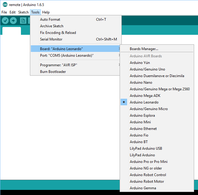
In the Arduino IDE I selected “Arduino Leonardo” from Tools->Board menu and select the correct com port under Tools-Port, and flashed the new software to my board.
Hardware
With that done all that was left was soldering up some wires and connecting them to the button.
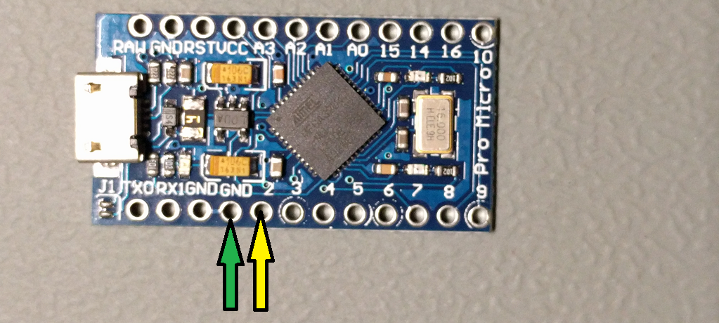
I soldered a piece of yellow wire to pin 2 of my board and a piece of green wire to the near by ground pin as shown below.
Then I just had to attach an exposed section of the other side of the wires to the screw terminals on the switch. On the switch I bought there was a side labeled “A” and a side labeled “B”.

Using a multimeter set on continuity test I determined the conditions of the connections between terminals with the switch depressed and released. On my switch the two terminals within the green side labeled “A” were closed when the push button was pressed, and the two terminals on the orange side labeled “B” were opened once the button was pressed.
Usage Notes
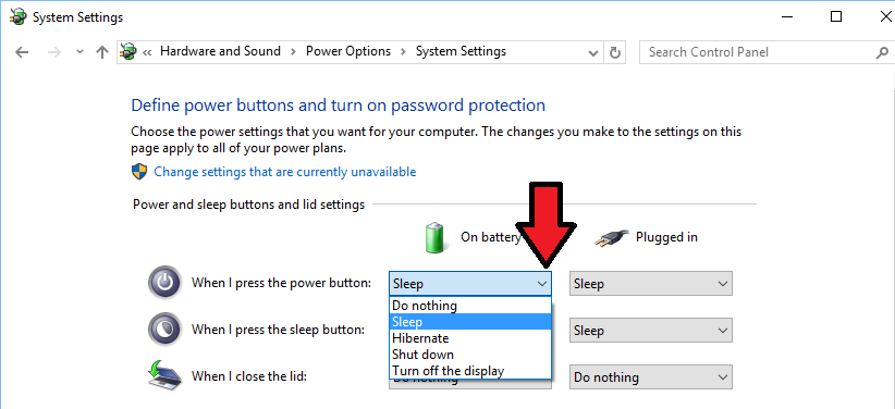
The effect of the power button can be changed in the OS. In Windows 10 you can get to this under Power Options as shown below.

I have mine set to sleep, which looks a bit cooler/quicker on the video above, and was less time consuming during testing and troubleshooting.
Bill of Materials
“Emergency Stop” Push Button
https://www.amazon.com/gp/product/B00MJVMV32
Red USB cable
https://www.amazon.com/gp/product/B013DO561W
“Pro Micro” ATmega32u4 “arduino Leonardo”-like board
https://www.amazon.com/gp/product/B012FOV17O
Resources
Sending HID Media Key (modified this)
http://stefanjones.ca/blog/arduino-leonardo-remote-multimedia-keys/
USB HID Usage Tables
http://www.usb.org/developers/hidpage/Hut1_12v2.pdf
Leave a Reply