Category: Raspberry Pi

  • Raspberry Pi RTS / CTS Flow Control

    Raspberry Pi RTS / CTS Flow Control

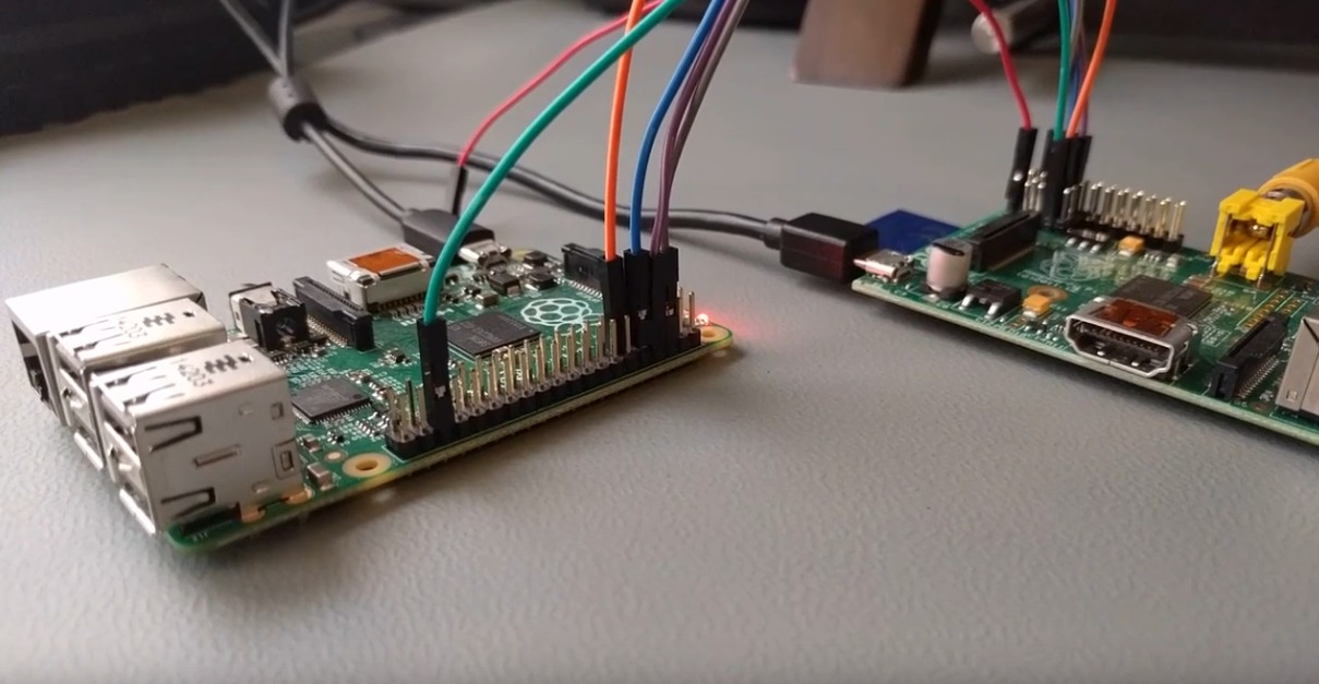
    I had need of a 3.3v TTL serial interface to reprogram a device I was working on. Looking around I realized I had mostly 5v logic USB to serial adapters. I figured the Raspberry Pi would work well enough, but I also needed hardware flow control. As it turned out the Pi can do RTS / CTS flow control, so I documented my notes on the subject here in case I or someone else might find them useful in the future.

    What is flow control

    In serial communications occasionally we need a way to tell the device or computer on the far-end of our serial connection that we need it to shut up for a bit while we collect our thoughts. Flow control exists for this purpose, although it is not a requirement of serial communication. Modern devices are fast, with large buffers for collecting incoming data, and often times flow control is omitted, particularly if data loss isn’t critical.

    Flow control can be done in software (Xon/Xoff) by sending special control characters to say stop or start the data flow. This creates some hassle since, particularly in the transmission of binary data, those control characters might come up naturally without the intent to change the flow of data. If you’ve ever accidentally frozen your Linux terminal (^s / ^q) you know what I’m talking about.

    Flow control can also be done out of band of the data transmission using dedicated signal pins/wires, we call this hardware flow control. Serial communications are old, there are a lot of variations so it probably isn’t much of a surprise to learn that there are multiple ways of doing hardware flow control. The most common are RTS / CTS and DTR / DSR. We are focusing on RTS / CTS, although DTR is still useful to know about (it gets used for example in programming the Arduino, to trigger a reset of the Arduino before programming). Because we can arbitrarily set the state of RTS and DTR via software we can abuse them to signal all sorts of stuff to connected hardware beyond just flow control.

    RTS stands for “Request to Send”, and in the current common use it is a terrible name for what it actually does. The name implies that it signals a request to send data to the equipment on the other side of the serial connection. CTS stands for “Clear to Send”, and as we might (correctly) assume it is a signal being sent to us from the far-end that indicates we are cleared to send our data. The problem with this is that it is only half-duplex (it goes just one way). How could we tell the far-end that we aren’t ready to receive data? Originally this was actually how it worked, it was intentionally half-duplex and it was designed with some rather old modem technology in mind.

    RTR or “Request to Receive” is probably a better name for RTS as it is used today, and some people prefer to use this term instead. We, or rather the UART controlling our communication doesn’t actually change the state of RTS when it wants to transmit data. RTS/RTR gets changed when the UART is unable to receive any more data from the far-end. This probably indicates that our hardware receive buffer is full and hasn’t been read and emptied out by software on our system yet.

    On the Raspberry Pi RTS is set low (0v) as long as the Pi’s UART is ready to receive data. If it can’t handle more incoming data it sets RTS high (3.3v). Our Pi should only send data to the far-end when the state of our CTS pin reads low and we should stop sending data if our CTS pin is high. So now we’ve got a working plan for bi-directional flow control. Our RTS goes to the CTS of the far-end and the far-end RTS goes to our CTS (and hopefully we both agree on the logic levels).

    In our serial connection RTS and TX are our outputs, and CTS and RX are our inputs.

    Where are the RTS / CTS pins?

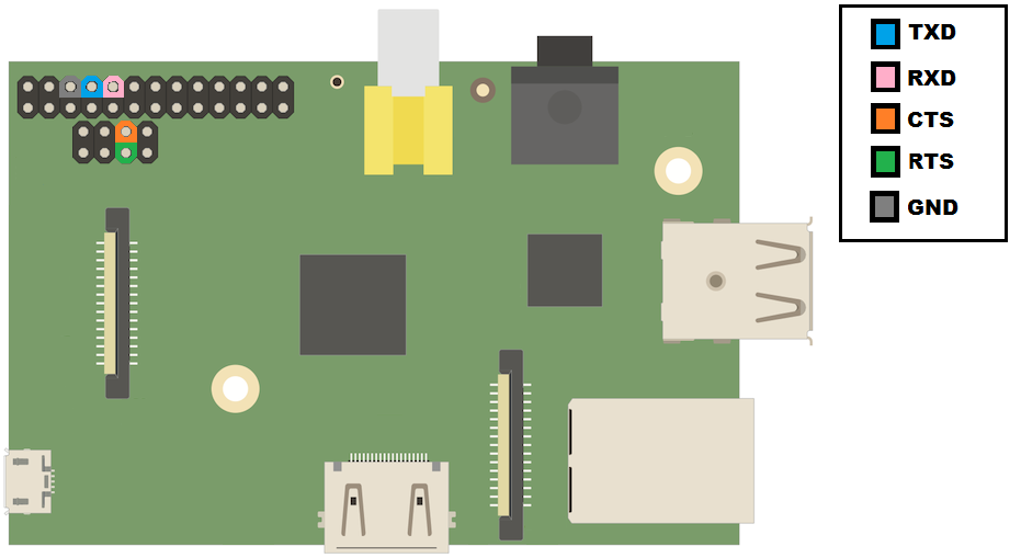
    On older versions of the Raspberry Pi with 26-pin GPIO header, you need to solder on an additional 2×4 section of dual row male 0.1″ (2.54mm) header pins on the unpopulated “P5” header.

    On early Pi’s like the original version B, this header isn’t there, and so if you are still using one of those devices you’ll probably need to work something else out.

    The P5 header is actually intended to be mounted on the bottom of the Pi board (opposite to the 26 pin GPIO). That seemed pretty crazy to me, because the thing would obviously never lay flat or fit in standard cases that way. I think the intent is to avoid interfering with Raspberry Pi hats that sit on top of the 26-pin header, but even with P5 populated on the reverse side of the board (same side as the 26-pin headers) I was able to put the one hat I have on my Pi. Your miles may vary of course. If you do put the P5 header on the same/sane side of the board as the 26 pin header keep in mind that many of the pin-outs you run into online might be mirrored.

    To remove ambiguity I’ve just colored the correct pins below rather than giving pin or GPIO numbers:

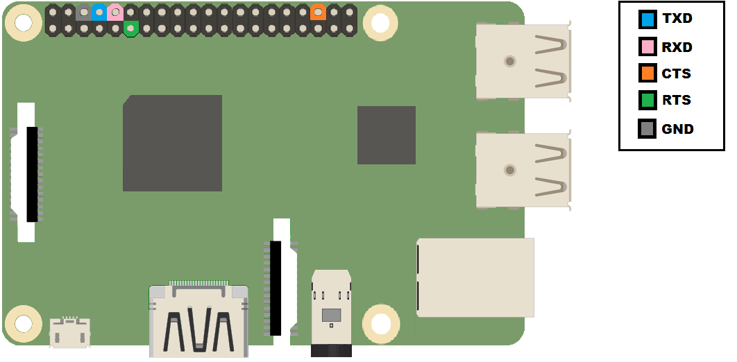
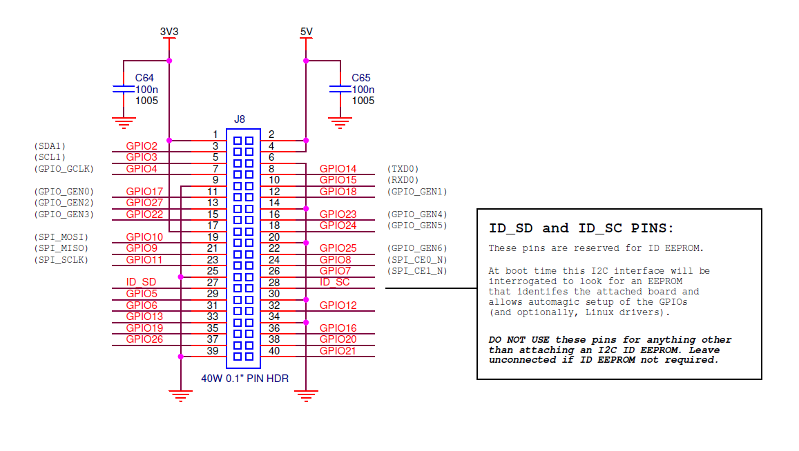
    On newer Raspberry Pis with the 40-pin header, this is much easier, there is nothing to solder first:

    Enabling RTS / CTS flow control

    OK, so now we’ve got the physical connections handled, but we still need to enable the RTS/CTS mode of these pins. As you might know several (most) of the Raspberry Pi GPIO pins live double (or triple) lives. By instructing the Broadcom SoC to enable the alternate functions we can get additional hardware features, I2C, hardware flow control for our UART, etc.

    We need to change a bit of memory to inform the Broadcom SoC which function of the GPIO we want. An easy way to do this for RTS / CTS is to use Matthew Hollingworth’s rpirtscts utility:

    https://github.com/mholling/rpirtscts

    root@raspberrypi:~# rpirtscts
    Version: 1.5
    Usage: rpirtscts on|off
    Enable or disable hardware flow control pins on ttyAMA0.

    For 26 pin GPIO header boards:
    P5 header pins remap as follows:
        P5-05 (GPIO30) -> CTS (input)
        P5-06 (GPIO31) -> RTS (output)

    For 40 pin GPIO header boards:
        P1-36 (GPIO16) -> CTS (input)
        P1-11 (GPIO17) -> RTS (output)

    You may also need to enable flow control in the driver:
        stty -F /dev/ttyAMA0 crtscts

    The last little note about stty in the rpirtscts help message is useful to mention. If you are using software that is aware of hardware flow control (i.e. will use the ioctl syscall to enable / disable it) you don’t need to worry about setting the stty option. If you are sending input/output from programs over serial that are not specifically intended to be sent over a serial line, then you will probably want to tell stty to tell the system to enable RTS / CTS. The rpirtscts utility sets the Broadcom SoC to use the RTS / CTS alternate functions of the applicable GPIO pins, but it doesn’t tell Linux to enable RTS / CTS flow control.

    Current versions of rpirtscts can detect which Raspberry Pi you are using and take the appropriate action for that hardware.

    Using rpirtscts on the 26-pin Pi looks like this:

    root@raspberrypi:~# rpirtscts on
    26-pin GPIO header detected
    Enabling CTS0 and RTS0 on GPIOs 30 and 31

    The 40-pin Pi is set with the same command, but uses the (different) correct GPIOs for that hardware:

    root@raspberrypi:~# rpirtscts on
    40-pin GPIO header detected
    Enabling CTS0 and RTS0 on GPIOs 16 and 17

    As an alternative to rpirtscts, if you’d like the CTS / RTS alternate function to be the usual function of your particular Pi (and persist across reboots) you might instead consider configuring a device tree overlay:

    https://www.raspberrypi.org/documentation/configuration/device-tree.md

    Also note that the Raspberry Pi 3 uses the ttyAMA0 port for driving Bluetooth, so there are some additional considerations to deal with. Thankfully Weave has this is all well documented here:

    http://www.deater.net/weave/vmwprod/hardware/pi-rts/

    Good luck!

    Check out http://www.pighixxx.com/ for great art of popular electronics.

  • Santa Hatifyer v1.0

    Santa Hatifyer v1.0

    Well, it’s Christmas time again. I really haven’t had a lot of blog posts since last Christmas, so my 2013 desk-decorations (deskorations?) are still fresh on my mind. I cheated this year, and didn’t stick to stuff I had on hand (although at the core is a Raspberry Pi, which the office had available).

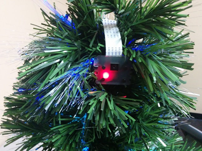
    I purchased one of those cool new Raspberry Pi camera modules and stuck it in a [faux] Christmas tree. These use the Pi’s camera serial interface (CSI) port which may provide better frame rates than processing from some USB webcams. I didn’t benefit from any of that efficiency in my project, but that’s my own fault.

    rpi_cam_xmas_tree

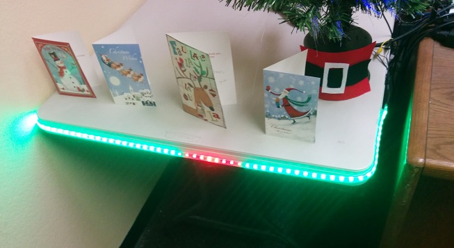
    I used a 60 LED 1 meter “Neopixel” WS2812B series from Adafruit to decorate the folding table holding my tree and greeting cards. My coworker Eric programmed a Larson scanner sequence (think of the lights on the KITT car from the television show Knight Rider, or the cylons from Battlestar Galactica). He wrote some other sequences as well, but they were all pretty hard to capture with my camera due to the brightness of the LEDs.

    christmas_cylon

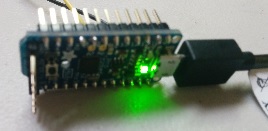
    We drove these with an Arduino compatible “Trinket Pro” also from Adafruit, although they could have been driven by the Pi itself with some extra effort. The Trinket route was pretty straight forward thanks to the Adafruit Neopixel library.

    arduino_trinket

    A monitor connected to the Raspberry Pi displays a festive youtube video of a fire and falling snow. This 2 hour long video plays on a loop, unless it is interrupted.

    While the video plays a Python script takes images from the Raspberry Pi camera module and uses OpenCV to detect faces. When a face is found a Santa hat is placed on the subject’s head (or thereabouts) and the picture is displayed to the viewer in a greeting card-esque format. The hat is scaled to fit the head of the individual subject, and multiple subjects are supported. The photos are of course saved for future embarrassment.

    xmascam_eric

    The script is ugly, and as I said earlier pretty inefficient (unnecessary disk I/O and format conversions for starters). The slowness is amplified by the limited resources available on the Pi. No doubt this can be done better, quicker, and probably as a real-time video. Here it is regardless. The background comes from scigola’s contribution over at openclipart.org (thank-you).

    https://github.com/ethertubes/santa_hatifyer

    xmasvision.py

    #!/usr/bin/env python

    # vim: tabstop=8 expandtab shiftwidth=4 softtabstop=4
    import cv2
    import sys
    import io
    import time
    import picamera
    import picamera.array
    import os
    import pygame

    CAMERA_WIDTH = 640
    CAMERA_HEIGHT = 480

    # Taken from "Capturing to an OpenCV object"
    # http://picamera.readthedocs.org/en/latest/recipes1.html

    # Create the in-memory stream
    stream = io.BytesIO()

    face = 0
    while face == 0:
        # Acquiring pic
        with picamera.PiCamera() as camera:
            camera.resolution = (CAMERA_WIDTH, CAMERA_HEIGHT)
            camera.vflip = True
            time.sleep(1)
            with picamera.array.PiRGBArray(camera) as stream:
                camera.capture(stream, format=‘bgr’)
                # At this point the image is available as stream.array
                image = stream.array

        # Adapted from "Haar-cascade Detection in OpenCV"
        # http://docs.opencv.org/trunk/doc/py_tutorials/py_objdetect/py_face_detection/py_face_detection.html
        face_cascade = cv2.CascadeClassifier(‘haarcascade_frontalface_default.xml’)

        # Got pic, checking for faces
        gray = cv2.cvtColor(image, cv2.COLOR_BGR2GRAY)
        faces = face_cascade.detectMultiScale(image, 1.3, 5)

        if len(faces) > 0:
            face = 1
            print "Found Face! "
            cv2.imwrite(‘foundface.jpg’, image)

    cv2.destroyAllWindows()

    # driver selection routine borrowed from:
    # https://web.archive.org/web/20130601053413/http://www.karoltomala.com/blog/?p=679

    screen = None;

    drivers = [‘fbcon’, ‘directfb’, ‘svgalib’]

    for driver in drivers:
        if not os.getenv(‘SDL_VIDEODRIVER’):
            os.putenv(‘SDL_VIDEODRIVER’, driver)
        try:
            print "trying: " + driver
            pygame.display.init()
        except pygame.error:
            print ‘Driver: {0} failed.’.format(driver)
            continue
        found = True
        break

        if not found:
            raise Exception(‘No suitable video driver found!’)

    original_width = pygame.display.Info().current_w
    original_height = pygame.display.Info().current_h

    # match camera/image resolution
    width = CAMERA_WIDTH
    height = CAMERA_HEIGHT

    # Use the face photo as our canvas
    screen = pygame.display.set_mode((width, height))
    pygame.mouse.set_visible(False)
    bg = pygame.image.load(‘foundface.jpg’)
    bg = pygame.transform.scale(bg, (width, height))
    screen.blit(bg, bg.get_rect())

    # hat is longer on the right than the wearable
    # area (because of the little puff ball) tweak
    # value for your own hats
    hat_offset = 330

    # put the hat on the cat
    if len(faces) > 0:
        for (x,y,w,h) in faces:
            hat = pygame.image.load(‘hat.png’).convert_alpha()
            hat_size = int((hat.get_width() – hat_offset) / w)
            if hat_size < 1:
                hat_size = 1
            hat_offset = int(hat_offset * (1.0 / hat_size))
            hat = pygame.transform.scale(hat, (int(hat.get_width() * (1.0 / hat_size)), int(hat.get_height() * (1.0 / hat_size))))
            hat_w = hat.get_width()
            hat_h = hat.get_height()
            #pygame.draw.rect(screen, (255, 0, 0), (x, y – hat_h, hat_w, hat_h), 1) # hat border, helpful for debugging
            print "x: " + str(x)
            print "y: " + str(y)
            # fudge placement a little to put hat on, rather than over
            fx = int(x * 0.96)
            fy = int(y * 1.04)
            screen.blit(hat, (fx, fy – hat_h, hat_w, hat_h)) # fudge placement a little to put hat on, rather than over
            #pygame.draw.rect(screen, (0, 255, 0), (x, y, w, h), 1) # face border

    # Uncomment if you want to see the intermediary face + hat photo
    #pygame.display.update()
    pygame.image.save(screen, ‘hatted.png’)

    # Resize canvas to fit monitor
    width = original_width
    height = original_height

    # load background and photo (with hat) into objects
    # display background over photo, allowing transparent region to
    # show the photo behind it.
    screen = pygame.display.set_mode((width, height))
    bg = pygame.image.load(‘xmascam.png’).convert_alpha()
    bg = pygame.transform.scale(bg, (width, height))
    photo = pygame.image.load(‘hatted.png’)
    photo = pygame.transform.scale(photo, (int(1.339 * photo.get_width()), int(1.339 * photo.get_height())))
    screen.blit(photo, (622, 115, photo.get_width(), photo.get_height()))
    screen.blit(bg, bg.get_rect())
    pygame.display.update()

    time.sleep(10)
    sys.exit

    pygame.display.quit()

    This script is ran, the photos archived, and the fire video started/stopped by the following bash script

    watcher.sh

    #!/bin/bash

    facewatch() {
            if ! [ -d "./archive" ]; then
                    mkdir "./archive"
            fi

            while [ 1 ]
            do
                    ./xmasvision.py
                    stamp="$(date +%s)"
                    if [ -f "foundface.jpg" ]; then
                            mv foundface.jpg ./archive/foundface_$stamp.jpg
                    fi
                    if [ -f "hatted.png" ]; then
                            mv hatted.png ./archive/hatted_$stamp.png
                    fi
            done
    }

    facewatch &
    while [ 1 ]
    do
            # if "hatted.png" exists then the thing should display soon
            # so stop the fire video
            if [ -f "hatted.png" ]; then
                    if ! [ -z "$(ps aux |grep -i omxplayer.bin |grep -v grep)" ]; then
                            killall omxplayer.bin
                    fi
            fi
            # start the fire video if needed
            if [ -z "$(ps aux |grep omxplayer.bin |grep -v grep)" ]; then
                    omxplayer video/Christmas\ Yule\ Log\ Fireplace\ with\ Snow\ and\ Crackling\ Fire\ Sounds\ \(HD\)-y_VD92xKS5w.mp4 &
            fi
            sleep 1
    done

    Happy Holidays

  • PartyTube – YouTube-video powered party jukebox for RPi

    PartyTube – YouTube-video powered party jukebox for RPi

    Last month I had a Halloween party. Many people don’t seem to like the music I like, and I generally don’t like their music either. While planning my party it occurred to me that the music selection should be a collaborative process that included the guests. I spent the next few hours making my “Partytube” script, a collaborative Youtube-video powered jukebox for the Raspberry Pi. It’s just a series of quick and dirty little scripts that glue existing projects together for my purpose.

    A pygame based display shows the song queue momentarily before the next music video begins playing.

    partytube_playlist_small

    You can download the project from GitHub: https://github.com/ethertubes/partytube

    Install

    Installation requires a few important third-party programs. First start with a copy of Raspbian, this will include most of the python/pygame stuff, the omxplayer and other things presumed to be in the working environment.

    You’ll need the youtube-dl youtube ripping script available at https://github.com/rg3/youtube-dl, but it’s quicker just to download it from yt-dl.org (see below). It’s a fairly large and complex script, and not really knowing what is in it, I decided against running it as root. I made a dedicated youtube user on my Pi for the purpose of running the youtube-dl script.

    root@raspberrypi:~# adduser youtube
    Adding user `youtube’ …
    Adding new group `youtube’ (1004) …
    Adding new user `youtube’ (1001) with group `youtube’ …
    Creating home directory `/home/youtube’ …
    Copying files from `/etc/skel’ …
    Enter new UNIX password: youtube
    Retype new UNIX password: youtube
    passwd: password updated successfully
    Changing the user information for youtube
    Enter the new value, or press ENTER for the default
            Full Name []: Youtube Video Fetcher
            Room Number []:
            Work Phone []:
            Home Phone []:
            Other []:
    Is the information correct? [Y/n] y

    root@raspberrypi:~# su – youtube
    youtube@raspberrypi~$ curl https://yt-dl.org/latest/youtube-dl -o youtube-dl
    youtube@raspberrypi~$ chmod a+x youtube-dl
    youtube@raspberrypi~$ ./youtube-dl
    Usage: youtube-dl [options] url [url…]

    I also made some working directories, and downloaded and unpacked my scripts

    youtube@raspberrypi~$ mkdir input
    youtube@raspberrypi~$ mkdir output
    youtube@raspberrypi~$ mkdir archive
    youtube@raspberrypi~$ wget https://github.com/ethertubes/partytube/archive/master.zip
    –2014-11-28 15:11:02–  https://github.com/ethertubes/partytube/archive/master.zip
    Resolving github.com (github.com)… 192.30.252.130
    Connecting to github.com (github.com)|192.30.252.130|:443… connected.
    HTTP request sent, awaiting response… 302 Found
    Location: https://codeload.github.com/ethertubes/partytube/zip/master [following]
    –2014-11-28 15:11:08–  https://codeload.github.com/ethertubes/partytube/zip/master
    Resolving codeload.github.com (codeload.github.com)… 192.30.252.146
    Connecting to codeload.github.com (codeload.github.com)|192.30.252.146|:443… connected.
    HTTP request sent, awaiting response… 200 OK
    Length: unspecified [application/zip]
    Saving to: `master.zip’

        [  <=>                                                                                                                                                                                               ] 247,104      923K/s   in 0.3s

    2014-11-28 15:11:14 (923 KB/s) – `master.zip’ saved [247104]
    youtube@raspberrypi~$ unzip master.zip
    Archive:  master.zip
    361942a1cf79d40976e4e40ad6fab6263fc775fd
       creating: partytube-master/
      inflating: partytube-master/LICENSE
      inflating: partytube-master/README.md
      inflating: partytube-master/YouTube-logo-light.png
      inflating: partytube-master/future_date.sh
      inflating: partytube-master/get_songs_http.sh
      inflating: partytube-master/get_songs_nfc.sh
       creating: partytube-master/output/
      inflating: partytube-master/output/none.jpg
       creating: partytube-master/php/
      inflating: partytube-master/php/get.php
      inflating: partytube-master/php/index.html
     extracting: partytube-master/php/playlist.txt
      inflating: partytube-master/php/save.php
      inflating: partytube-master/run.sh
      inflating: partytube-master/show_playlist.py
     extracting: partytube-master/url.png
      inflating: partytube-master/wood.jpg
      inflating: partytube-master/youtube-thumb.sh
      inflating: partytube-master/youtube-title.sh
    youtube@raspberrypi~$ rm master.zip
    youtube@raspberrypi~$ mv ./partytube-master/* .
    youtube@raspberrypi~$ rmdir partytube-master/
    youtube@raspberrypi~$ exit

    Originally I planned on guests submitting their song selections over the web. I figured it would be nice to have a QR code to save them the effort of typing in a URL on their smartphone. I installed the qrencode package available in Raspbian.

    root@raspberrypi:~# apt-get install libqrencode3 qrencode

    This way I can do something like:

    qrencode -o url.png -t PNG "http://www.example.org"

    to create an image that I can print and display near the television. You’ll probably want to include the text form of the URL in your printed signage as well in case people don’t have a QR reader program. Obviously, replace example.org with whatever your URL is. You’ll want to use a web server capable of serving php content. Upload the content from the “php” directory from partytube to the place you selected on your web server. Make sure that the file playlist.txt is readable and writable by the effective user ID of the web server. I would recommend using public web space rather than a server hosted on the Pi itself, this prevents guests from needing to be part of your local network, but if your Pi is publicly facing I suppose this isn’t an issue. Please keep in mind that there is really no thought put into the security of this hastily created project, and anyone who knows the URL can clear the submissions waiting to be collected by the partytube scripts.

    I showed a friend my script and he suggested it would be cool if I could add NFC support. Many new Android phones have NFC hardware that makes sharing website links as easy as bringing the phone in proximity to another phone or NFC capable device. I actually had a PN532 NFC/RFID controller breakout board from Adafruit.com that I purchased to play with, but never got around to doing anything with, so this sounded like a good opportunity to use it. The Adafruit PN532 breakout board has a 3.3v TTL UART interface that makes connecting it to the Raspberry Pi a straight forward process.

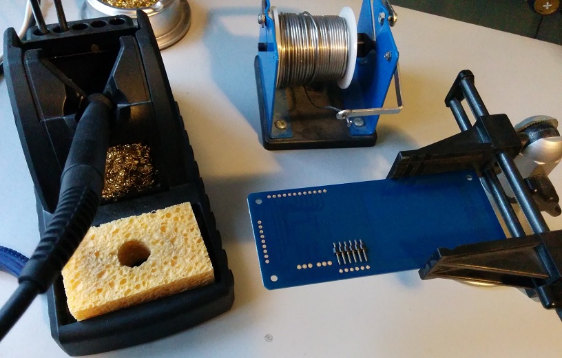
    Solder some header pins on to the board in the area marked “FTDICABLE
    nfc_uart_header

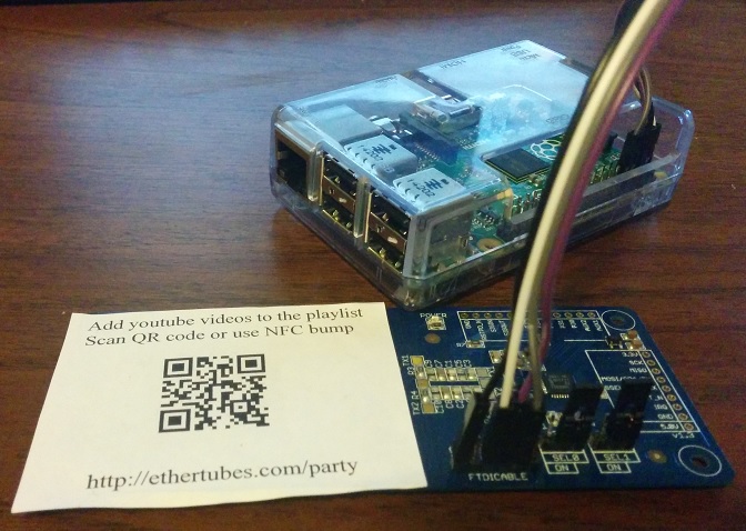
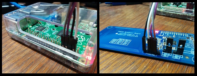
    Then use some female to female jumper wires to connect the the NFC board to the Pi.

    The RXD pin of the NFC board should go to the TXD pin of the Pi, and the TXD pin of the NFC board should go to the RXD pin on the Pi. You’ll also need to connect the ground pin of the NFC board to any of the ground pins available on the Pi, and connect the NFC board 5.0V pin to one of the 5v power pins on the Pi. Make sure to consult the latest documentation for your version of the Raspberry Pi in order to identify the correct pins as these could change with different versions of the Pi.

    bplus-gpioSource: http://www.raspberrypi.org/wp-content/uploads/2014/04/bplus-gpio.png

    I also soldered the headers for the jumpers which let me select between operating modes (UART, SPI, or I2C), but this isn’t required since the default mode is UART.

    nfc_pi_uart

    I printed my QR code and some instructions for guests and adhered it over the antenna area on the NFC board.

    partytube_nfc_label

    So, of course we need a way to be able to get data from the NFC reader now. There is a python module that can interface to this reader available at https://launchpad.net/nfcpy with documentation at http://nfcpy.readthedocs.org/en/latest/. The sample beam.py script that comes with the nfcpy module source seems to do what I want, so I just used that.

    root@raspberrypi:~# apt-get install bzr
    root@raspberrypi:~# cd /usr/local/src
    root@raspberrypi:/usr/local/src# bzr branch lp:nfcpy

    I added the youtube user to the dialout group to give it access to the Pi’s TTL UART port on /dev/ttyAMA0.

    root@raspberrypi:/usr/local/src# adduser youtube dialout
    Adding user `youtube’ to group `dialout’ …
    Adding user youtube to group dialout
    Done.

    You’ll also want to disable the serial console setup on /dev/ttyAMA0 to make sure that doesn’t interfere with the communications to the NFC board. Make sure you have ssh access or some other way to access your Pi besides serial console, and then edit /etc/inittab and comment out the ttyAMA0 line:

    #Spawn a getty on Raspberry Pi serial line
    #T0:23:respawn:/sbin/getty -L ttyAMA0 115200 vt100

    Edit /boot/cmdline.txt and remove the console=ttyAMA0,115200 portion of the line

    dwc_otg.lpm_enable=0 console=ttyAMA0,115200 console=tty1 root=/dev/mmcblk0p2 rootfstype=ext4 elevator=deadline rootwait

    At this point it’s probably a good idea to reboot the Pi. You should be able to test the NFC board by running the command:

    root@raspberrypi:~# sudo -u youtube /usr/local/src/nfcpy/examples/beam.py –device tty:AMA0:pn53x recv print

    Try beaming a URL from your phone over NFC, you should see the URL in the on-screen output.

    All that should be left is to hook the Pi up to an HDMI display with audio support like a television set or multimedia receiver. Omxplayer can be also output through the analog sound port using the -o local command line argument, but you’ll have to edit the script to make use of that if you require it.

    To start the whole thing in motion run the run.sh script as root

    root@raspberrypi:# cd ~youtube
    root@raspberrypi:/home/youtube# ./run.sh

    Songs are played in the order of their unix timestamp. I added a bunch of song selections before the party started because I didn’t want it to be boring and quiet until guests had a chance to figure out the partytube process. I didn’t want my playlist to preempt their choices though, so I modified the time/date of my selections to keep them at the bottom of the playlist queue (setting their dates to the future). Take a look at the future_date.sh script if you’d like to do something similar.

    Explanation

    There are a hodgepodge of shell scripts at work here, so a brief description is probably in order.

    save.php

    This file should be hosted on a web server capable of running php and accessible to party guests. If collects a submitted youtube URL and writes it to the playlist.txt file within the same directory

    get.php

    This displays the contents of playlists.txt and then truncates the file. It should be hosted on a web server capable of running php alongside save.php and accessible to the Raspberry Pi.

    run.sh

    Before running this script, the “URL=” variable should be modified to reflect the location where save.php and get.php are hosted on the web (for example http://example.org/party would be correct if http://example.org/party/save.php and http://example.org/party/get.php are hosted at those locations).

    After starting the run.sh script, the URL specified in that script is turned into a QR code image which will be displayed on screen between songs. The NFC and web-based URL submission collection scripts are started in the background. The web-based collection script is passed (as a command line argument) the URL the user specified with “/get.php” appended. Next the show_playlist.py is ran. After show_playlist.py exists the omxplayer displays the next music video (as determined by timestamp) from the “./output” directory. Once the video is done playing it and it’s corresponding meta data are moved to the “./archive” directory, show_playlist.py is called again and the cycle repeats indefinitely until run.sh receives the SIGEXIT or SIGTERM signal, at which time it attempts clean up by killing all screen sessions owned by the youtube user and the omxplayer before exiting.

    show_playlist.py

    The show_playlist.py script is started which shows the aforementioned QR code as well as any songs currently in the queue. The “queue” consists of files in the “./output” directory. Songs are sorted according to their timestamp, from oldest to newest. All video files should have a corresponding (same base filename) text file containing the video title and a thumbnail image. Show_playlist.py displays the contents of these corresponding files and a list of the next few songs to be played. After a few seconds of displaying this information to the screen the script exits.

    get_songs_nfc.sh

    The get_songs.nfc.sh script runs the beam.py example from nfcpy and parses the output for URLs containing ‘youtube‘. The youtube video ID is parsed out and used as the filename for the video and corresponding files. The youtube URL is handed to youtube-dl which downloads the Youtube video to the “./input” directory. Once the download is complete the video ID is passed to the “youtube-title.sh” and “youtube-tumb.sh” scripts which save the video title and thumbnail image. The title, thumbnail and video file for all videos in “./input” are processed and moved to the “./output” directory. If a file in “./input” is not an mp4 file it is deleted. This process repeats until the script is killed.

    get_songs_http.sh

    The get_songs_http.sh script collects song submissions from a remote website. It takes one command line argument: the web address of a list of youtube URLs (one per line). This address is specified in the run.sh script. For each line in the downloaded list get_songs_http.sh passes the URL to youtube-dl to download the video. Youtube-dl saves the video to the “./input” directory. Once the download is complete the Youtube ID of the downloaded video is passed to the “youtube-title.sh” and “youtube-tumb.sh” scripts which save the video title and thumbnail image. The title, thumbnail and video file for all mp4 videos in the “./input” directory are processed and moved to the “./output” directory. If a file in “./input” is not an mp4 file it is deleted. The script waits 60 seconds before repeating this process. This continues until the script is killed.

    Well, I think this covers everything, it’s a kludge that’s for sure, but it worked well for my party. Maybe I’ll make some updates for my next gathering.